Context, Containers, Components and Code
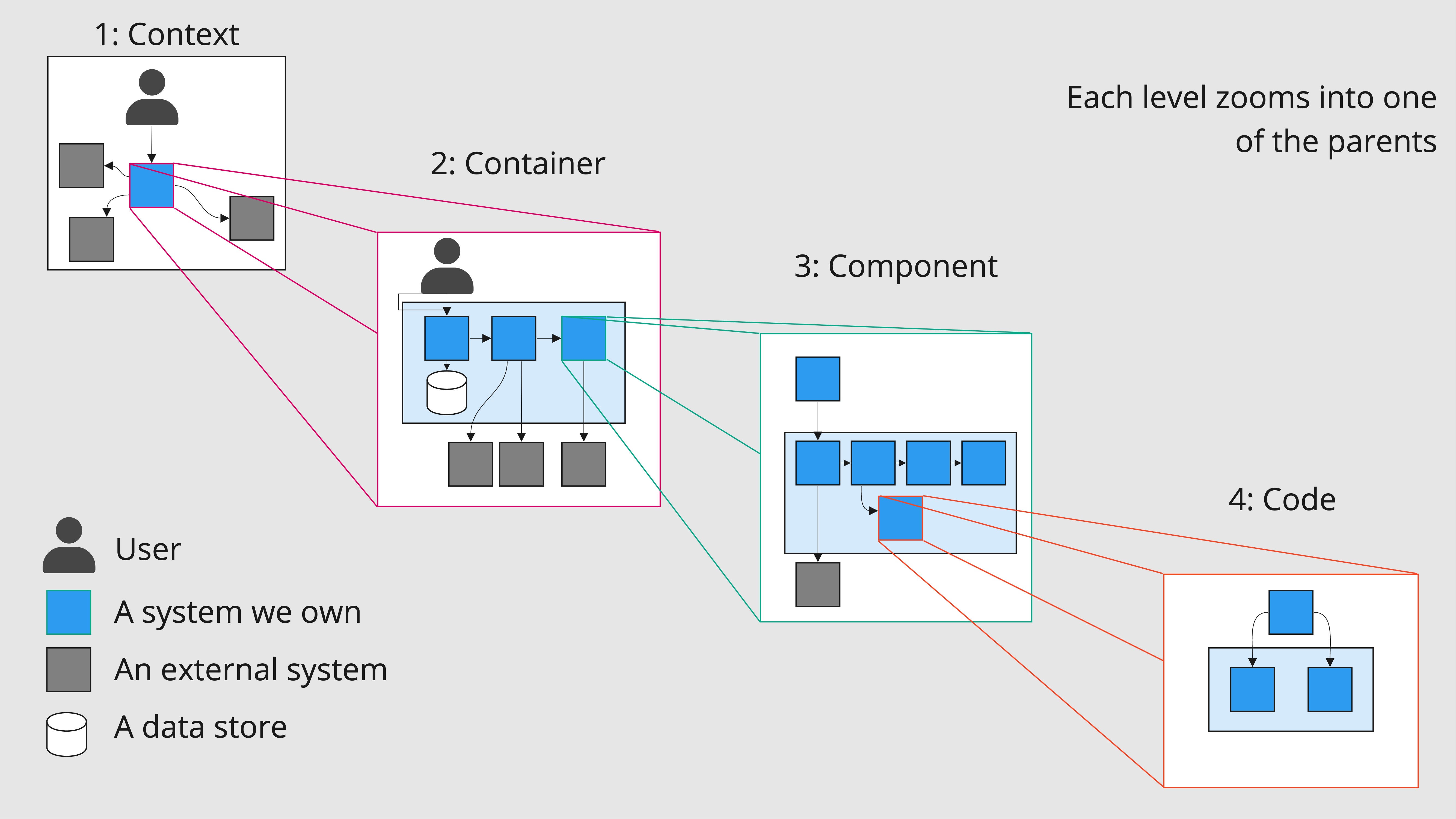
A C4 diagram is a visual tool to assist in understanding how a some thing fits with other things in its environment. There are four levels Context, Containers, Components, and Code, hence the name C4.

Each step down takes a single piece from the level above and examines what’s going on inside it, the idea is that anyone that works with or in proximity to a system should find value in at least one part of the diagram. Just as the builder needs to know which walls are integral for support but may be less interested in the direction they face, the Product Manager often needs to be aware which systems we integrate with or have the power to change. Conversely the interior designer may be very interested in wall orientation as to understand where the light will be, while the engineer needs to understand not only if they can but where to make a change.
Context
Intention: How a piece of software fits in with environment around it.
Audience: Everyone. Anyone that works with this software will need to know who’s responsible for it, so will need to know how it fits into the larger ecosystem.
Containers
Intention: What are the primary blocks of the software? How do they interact?
Audience: The team. Product managers and designers need to be aware what blocks they’re interacting with.
Components
Intention: How does a container function? How are responsibilities separated?
Audience: Engineers and Architects. This level represents a larger scale map of the environment.
Code
Intention: What are the dependencies? How do classes and functions interact?
Audience: Engineers. This level has a lot of additional detail that may not be useful to those not working directly on the code.
As per usual of course, this all makes a lot more sense with an example…
A Unicorn Rental Agency
Let’s say you have a herd of unicorns. People like unicorns, and as such would like to rent them for their parties, business events, or a random Tuesday for the fun of it. You started manually taking these orders over the phone, but they’ve surged in popularity and now you need a system to organise this for you.
What might that look like?
Context
Before we can get too far into it, we need to understand some of the key building blocks of a C4 diagram. First we have users / other systems that interact with ours. The directionality of arrow indicates what is responsible for instantiating the action. Grey boxes are external systems, and blue are ones that we own.

From this diagram we gain a general idea about what’s going on. Users request a unicorn, some external system is responsible for taking the payment and the user is sent emails updating them on the state of their request. Nice! We get all that from a single diagram. We see that we don’t own the email system, nor the payments, so no complexities for us around storing credit card information etc.
Containers
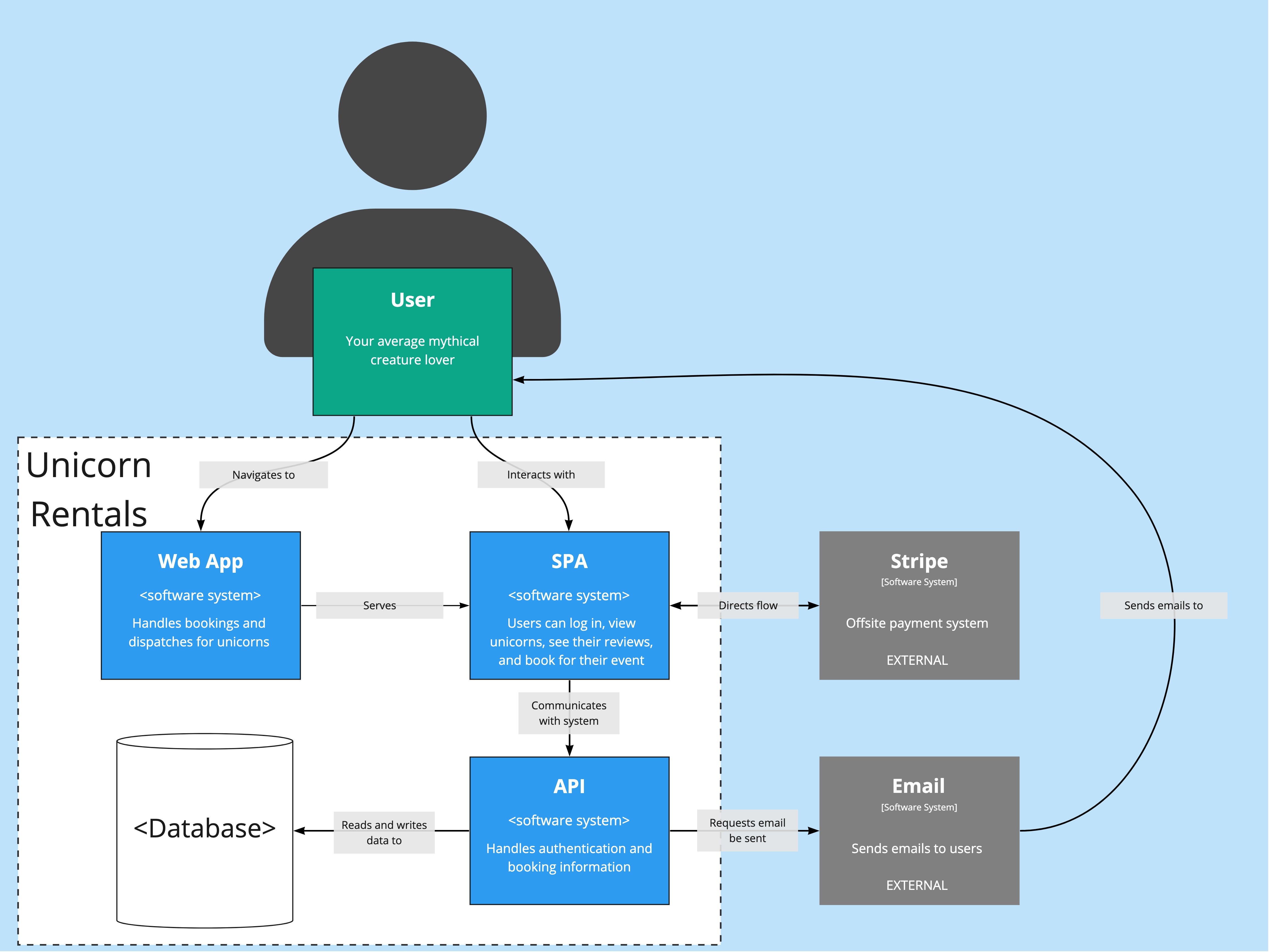
Next is the containers. We have this Unicorn Rentals software system, but no real idea right now what it is capable of.

Right, okay. This diagram is telling us that there’s only a few key blocks to this system. There’s a web application that serves the Single Page Application, which is in turn responsible for talking to our API for all its needs.
Whats more however, is that not only can we can see which blocks in our system are responsible for communicating with each other, but also with external services. The API isn’t responsible for talking to Stripe, the SPA is, and likewise the SPA cannot send an email itself, that seems to be some side effect from communicating with the API.
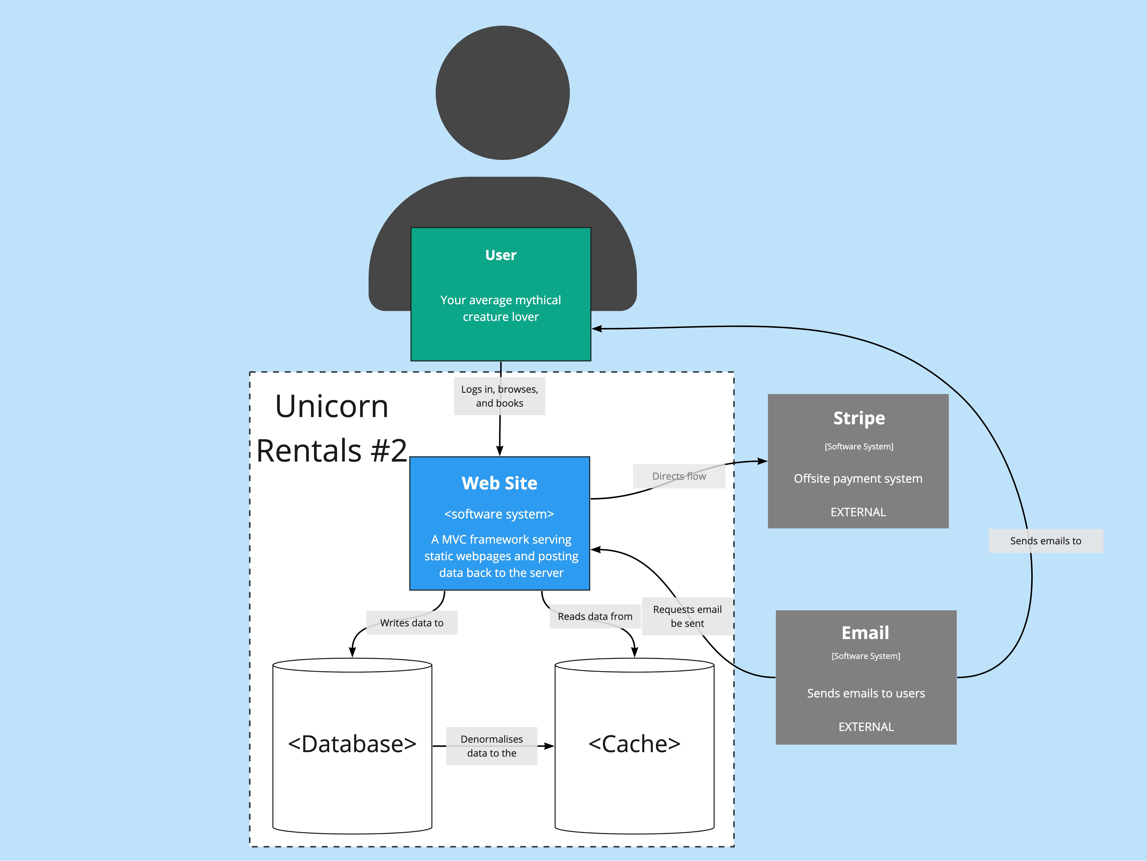
I don’t know about you, but that’s a lot of information packed into a single diagram. From these two alone, you should have a reasonable overview as to how this system works. For the sake of argument, I’ve included a different architecture below. What does this one tell you in comparison to the first?

Components
For each block in the container section we’d expect to see a corresponding component.

The component diagram displays a lot more detail than the previous two. At this point the document is probably only of interest to engineers, providing a map for how various pieces speak to one another.
It’s interesting to note here that there’s a Route Planning system in the API. Unicorns may be magical but they’re still subject to traffic laws.
Code
We’d now expect to see UML diagrams to explain how different code blocks interact. Generally these go into a little more detail than most require, and change too quickly for the diagrams to be accurate. As such they are not generally advised to do, and as such I won’t be doing them here. (At this point though, you should get the idea.)
Wow, that’s a lot
C4 diagrams may seem like a lot of effort to understand, and in some ways that’s true. What they really represent are abstractions, with each layer peering into a given block and seeing what’s inside. The first two levels can provide an immense amount of value to anyone that is responsible for the development of a system but does not build it, while the third level can help provide a useful map for those that do.
How far you go to is up to you, and while each one requires more maintenance than the last this is really one of the key advantages. Agile methodologies promote iterating quickly, so large, detailed architecture diagrams can be cumbersome. Instead C4 allows you to supply just the level of detail that is useful without immediately being out of date!